
How to Test a 70V/100V Ceiling Speaker Line Before Connecting the Amplifier

About Author: Kevin Wu
Founder & Principal Audio Engineer, LECOVITA
Specialize in acoustic engineering, high-fidelity speaker and amplifier design, precision manufacturing, sonic innovation, immersive audio solutions, and premium audio system development.
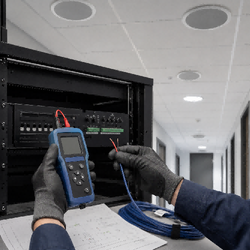
Table of Contents
How to Test a 70V/100V Ceiling Speaker Line Before Connecting the Amplifier
A commercial ceiling-speaker circuit should not be connected to its amplifier simply because every cable appears to be in the correct terminal.
An incorrect transformer tap, a short circuit, a disconnected speaker, or an unexpected branch can make the actual amplifier load significantly different from the original system design. If the fault is not found before power-up, the amplifier may enter protection mode, overheat, distort, or fail to operate correctly.
The recommended commissioning process is straightforward:
- Record every speaker and transformer tap.
- Calculate the total speaker tap load.
- Calculate the expected speaker-line impedance.
- Disconnect the line from the amplifier.
- Measure the circuit with a dedicated speaker-line impedance meter.
- Investigate any significant difference before applying audio power.
This guide explains each step without requiring special mathematical formatting or complicated series and parallel impedance calculations.
Quick Answer
To test a 70V or 100V ceiling-speaker line, first add together the transformer tap wattages of all speakers connected to the amplifier channel.
Next, calculate the theoretical line impedance using this formula:
Speaker-line impedance in ohms = Line voltage x Line voltage / Total speaker tap wattage
Disconnect the speaker cable from the amplifier and measure the isolated circuit with a suitable audio-frequency impedance meter.
Compare the measured value with the calculated value. A major difference can indicate an incorrect transformer tap, a missing speaker, an extra speaker, a cable fault, or a short circuit.
The calculated and measured values may not be exactly identical because real transformer and loudspeaker impedance changes with frequency.
Why Test a Speaker Line Before Power-Up?
A 70V or 100V distributed audio system normally connects multiple transformer-equipped speakers in parallel on the same amplifier channel.
This architecture makes it possible to operate many ceiling speakers over relatively long cable runs. Each speaker transformer has one or more wattage taps, and the selected tap determines the speaker’s nominal power draw at the system’s rated line voltage.
The system is easy to expand, but a visual inspection alone may not reveal every installation fault.
Pre-power-up testing can help identify:
- A speaker connected to the wrong transformer tap
- A speaker that was omitted from the circuit
- An extra speaker connected without being documented
- A disconnected cable branch
- A short circuit between the conductors
- A partial short caused by damaged cable insulation
- A speaker connected without the required transformer
- A circuit connected to the wrong amplifier zone
- Loose or intermittent terminal connections
- A difference between the system drawing and the actual installation
Measuring the completed circuit also provides a useful baseline. If the system develops a fault later, the original commissioning result can be compared with the new measurement.
Why a Normal Multimeter Is Not Enough
A 70V or 100V speaker line carries an audio signal. Its operating load is therefore an AC impedance rather than a simple DC resistance.
A conventional multimeter in resistance mode applies DC to the cable. It can be useful for finding a direct short or a completely open conductor, but it does not measure how the speaker transformers load the amplifier at audio frequencies.
A dedicated speaker-line impedance meter applies an AC test signal, commonly at an audio frequency such as 1 kHz. This provides a more useful indication of the load that the amplifier will see.
The meter’s test tone may also be audible through the connected speakers. An installer can use this tone to confirm that every speaker belongs to the correct zone and is connected to the circuit.
Important distinction
- DC resistance is what a standard resistance meter measures.
- AC impedance is the frequency-dependent load presented to the amplifier.
- These two readings should not be treated as the same value.
A multimeter can support basic continuity troubleshooting, but it should not replace a suitable impedance meter when commissioning a transformer-based speaker line.
Step 1: Prepare a Speaker Schedule
Before taking any measurements, prepare a schedule of all speakers connected to the circuit.
The schedule should include:
- Project name
- Amplifier channel or zone
- Speaker location
- Speaker model
- Selected line voltage
- Selected transformer tap
- Cable branch
- Total number of speakers
- Total calculated tap load
- Final measured impedance
- Test frequency, if shown by the meter
- Test date and technician
Do not use the loudspeaker driver’s maximum power rating when calculating the circuit load. Use the transformer tap selected during installation.
For example, a commercial ceiling speaker may have a 20W driver but may be connected to its 5W transformer tap. For the speaker-line calculation, the value to record is 5W.
Step 2: Calculate the Total Speaker Tap Load
Add together the selected transformer taps of every speaker connected to the amplifier channel.
Use this formula:
Total speaker load in watts = Number of speakers x Tap wattage per speaker
Example with identical taps
A circuit contains 12 ceiling speakers. Every speaker is set to the 5W tap.
The calculation is:
12 speakers x 5W = 60W total speaker load
The scheduled load for this circuit is therefore 60W.
Example with different taps
A zone contains six speakers with these transformer settings:
- Speaker 1: 10W
- Speaker 2: 10W
- Speaker 3: 5W
- Speaker 4: 5W
- Speaker 5: 2.5W
- Speaker 6: 2.5W
Add the selected taps:
10W + 10W + 5W + 5W + 2.5W + 2.5W = 35W
The total scheduled speaker load is 35W.
Step 3: Calculate the Theoretical Line Impedance
After calculating the total transformer tap load, estimate the theoretical impedance of the circuit.
Use this formula:
Speaker-line impedance in ohms = Line voltage x Line voltage / Total speaker tap wattage
A shorter version is:
Z = V x V / P
Where:
- Z means theoretical impedance in ohms
- V means the rated speaker-line voltage
- P means the total transformer tap load in watts
70.7V Speaker-Line Example
A 70.7V circuit contains 12 speakers set to 5W each.
First, calculate the total speaker load:
12 x 5W = 60W
Next, calculate the theoretical impedance:
70.7 x 70.7 / 60 = approximately 83.3 ohms
The expected theoretical line impedance is approximately 83.3 ohms.
For quick 70.7V calculations, the formula can be simplified to:
Approximate impedance in ohms = 5,000 / Total speaker tap wattage
For a 60W load:
5,000 / 60 = approximately 83.3 ohms
100V Speaker-Line Example
If the same 60W speaker load is used on a 100V system, the calculation is:
100 x 100 / 60 = approximately 166.7 ohms
The expected theoretical line impedance is approximately 166.7 ohms.
For quick 100V calculations, use:
Impedance in ohms = 10,000 / Total speaker tap wattage
For a 60W load:
10,000 / 60 = approximately 166.7 ohms
Quick Impedance Reference Table
| Total Speaker Tap Load | Approximate Impedance at 70.7V | Approximate Impedance at 100V |
|---|---|---|
| 25W | 200 ohms | 400 ohms |
| 50W | 100 ohms | 200 ohms |
| 60W | 83.3 ohms | 166.7 ohms |
| 100W | 50 ohms | 100 ohms |
| 150W | 33.3 ohms | 66.7 ohms |
| 200W | 25 ohms | 50 ohms |
These figures are theoretical nominal values. They should not be used as universal pass-or-fail limits.
Actual measured impedance may differ because transformer and loudspeaker impedance changes with frequency. Cable characteristics and other components in the signal path may also affect the result.
Step 4: Isolate the Speaker Circuit
The speaker cable must be isolated before it is connected to the test instrument.
Use the following procedure:
- Switch off the amplifier.
- Follow the amplifier manufacturer’s shutdown and isolation instructions.
- Disconnect the speaker cable from the amplifier output terminals.
- Confirm that the cable is not connected to another amplifier or energized source.
- Keep the disconnected conductors separated from each other.
- Prevent the bare conductors from touching the equipment rack.
- Identify the cable with its correct zone or circuit label.
- Check the impedance meter’s operating instructions before connecting it.
Do not connect a speaker-line impedance meter to an energized amplifier output unless the meter manufacturer specifically provides an approved procedure for doing so.
Constant-voltage amplifier outputs can produce substantial signal voltages. Installation and commissioning should be completed by qualified personnel in accordance with applicable electrical, fire, and building requirements.
Step 5: Measure the Speaker Line
Connect the impedance meter across the two isolated speaker-line conductors.
Select the appropriate measurement range and test frequency according to the instrument manufacturer’s instructions. Approximately 1 kHz is commonly used for speaker-line impedance measurement.
During the test:
- Record the displayed impedance.
- Record the test frequency if the meter displays it.
- Listen for the test tone at every speaker.
- Confirm that the correct zone is producing the tone.
- Identify missing or unusually quiet speakers.
- Compare the measured reading with the calculated theoretical value.
- Record the result in the commissioning document.
Do not expect the measured and calculated values to be perfectly identical. The purpose is to confirm that the measured circuit is reasonably consistent with the design and does not show evidence of a major wiring or loading problem.
Where the equipment manufacturer provides an acceptable measurement tolerance, follow that published tolerance.
How to Interpret the Measurement
Measured Impedance Is Much Lower Than Expected
A substantially lower impedance means the circuit may be presenting a heavier load than planned.
Possible causes include:
- One or more speakers set to higher wattage taps
- More speakers connected than shown on the system drawing
- An incorrect parallel branch
- A short circuit
- A partial cable short
- A damaged transformer
- A low-impedance speaker connected without the required transformer
- A 70V and 100V configuration error
- The wrong speaker cable being tested
Do not connect the circuit to the amplifier until the cause has been identified.
Measured Impedance Is Much Higher Than Expected
A substantially higher impedance generally indicates a lighter load or an incomplete circuit.
Possible causes include:
- One or more disconnected speakers
- Speakers set to lower wattage taps
- A broken cable conductor
- A loose connector
- An open cable branch
- A missing speaker
- An open relay or local control
- The wrong zone cable being tested
- An incomplete return connection
Use the impedance meter’s audible test signal, where available, to check each speaker individually.
The Reading Is Unstable
An unstable reading may indicate:
- A loose terminal
- An intermittent cable connection
- Damaged cable insulation
- A switching device in the circuit
- A supervisory module affecting the measurement
- A transformer connection that is not secure
- An unsuitable measurement range
- A circuit that has not been completely isolated
Divide the circuit into smaller sections until the unstable branch is located.
How to Find a Fault in a Branched Speaker Circuit
Large commercial speaker systems may contain several branches. Testing the entire circuit only tells the installer that a problem exists somewhere on the line.
A branch-isolation process can locate the fault more efficiently.
- Disconnect all branches at the distribution point.
- Measure each branch separately.
- Calculate the expected load of each branch.
- Compare each branch measurement with its scheduled load.
- Identify the branch with the unexpected result.
- Divide that branch again at the next accessible junction.
- Continue until the fault is isolated to a short cable section or small group of speakers.
Change only one connection at a time and record every measurement. Changing several transformer taps or cable connections simultaneously can make the original fault more difficult to identify.
Why One Missing Speaker May Be Difficult to Detect
In a small circuit, one disconnected speaker may create an obvious change in the measured impedance.
In a large circuit containing many parallel-connected speakers, however, the effect of one missing speaker may be relatively small. Normal changes caused by component tolerances or temperature can make that difference difficult to distinguish.
For this reason, impedance measurement should be combined with an audible speaker-by-speaker test.
The installer should confirm that:
- Every scheduled speaker produces the test tone.
- The tone comes from the correct zone.
- No unexpected speaker produces the tone.
- Every transformer tap matches the installation schedule.
- All cable branches are properly labeled.
Check Amplifier Capacity Separately
The impedance test verifies the approximate electrical load and basic integrity of the installed speaker circuit. Amplifier selection and configuration remain separate design tasks.
Before connecting the circuit, confirm that:
- The amplifier supports the selected 70V or 100V output mode.
- The total speaker tap load is within the amplifier channel’s rated capacity.
- The amplifier manufacturer’s required design margin has been applied.
- The output terminals are configured correctly.
- The correct zone is assigned to the output.
- Required protection settings have been configured.
- Any recommended high-pass filter is enabled.
- The amplifier is not set to a low-impedance output mode.
Transformer-based speaker circuits can present difficult loads at low frequencies. Some constant-voltage amplifiers include a high-pass filter specifically for this reason.
Follow the amplifier manufacturer’s instructions rather than applying one fixed headroom percentage or filter frequency to every project.
Final Pre-Power-Up Checklist
Before connecting the speaker cable to the amplifier, confirm the following:
- The speaker schedule is complete.
- Every speaker location has been checked.
- Every transformer tap has been recorded.
- The total tap load has been calculated.
- The theoretical impedance has been calculated.
- The circuit was isolated before measurement.
- A suitable audio-frequency impedance meter was used.
- Every speaker produced the test tone.
- The measured impedance was recorded.
- Unexpected measurements were investigated.
- Cable polarity was checked.
- Zone identification was confirmed.
- Amplifier output mode was verified.
- Amplifier capacity was verified.
- Required filters and protection settings were configured.
- The final results were added to the project documentation.
Conclusion
Testing a 70V or 100V ceiling-speaker circuit before power-up turns commissioning from guesswork into a documented engineering process.
The practical procedure is to record every transformer tap, calculate the expected load, isolate the circuit, measure it with a suitable speaker-line impedance meter, and investigate significant differences before connecting the amplifier.
This process can identify incorrect tap settings, missing speakers, unwanted branches, cable faults, and potentially dangerous loading conditions before they affect the amplifier.
For projects requiring 70V/100V commercial ceiling speakers, PA mixing amplifiers, speaker cables, or OEM/ODM system integration support, Lecovita can help review the proposed system architecture and product specifications before production or installation.
Frequently Asked Questions
Can I test a 70V speaker line with a normal multimeter?
A multimeter in resistance mode can help identify a direct short or a broken conductor. However, it measures DC resistance rather than the circuit’s operating AC impedance. Use a dedicated speaker-line impedance meter for transformer load verification.
Must the measured impedance exactly match the calculated value?
No. The calculated result is a nominal theoretical value. Actual impedance changes with test frequency and component characteristics. Use the equipment manufacturer’s tolerances and investigate significant differences.
Can an impedance meter identify one missing speaker?
It may identify a missing speaker in a small circuit. In a large zone with many parallel-connected speakers, the difference may be small. An audible test at every speaker should be included in the commissioning process.
Why must the cable be disconnected from the amplifier?
Disconnecting the cable protects the test instrument from an energized amplifier output and prevents the amplifier circuitry from influencing the measurement.
What does a low impedance reading mean?
A much lower-than-expected reading usually indicates a heavier load, higher transformer tap settings, extra speakers, an incorrect branch, or a wiring fault such as a short circuit.
What does a high impedance reading mean?
A much higher-than-expected reading usually indicates an incomplete circuit, disconnected speakers, lower transformer tap settings, a broken conductor, or a missing cable branch.
Is the impedance test enough to commission the complete system?
No. Final commissioning should also include polarity verification, functional audio testing, zone checking, amplifier configuration, level adjustment, coverage assessment, and project documentation.
References
- Biamp, “Constant-Voltage Speaker Systems.” Accessed September 1, 2026.
https://support.biamp.com/Vocia/Miscellaneous/Constant-voltage_speaker_systems - Biamp, “AudiaFUSION Impedance Monitoring.” Accessed September 1, 2026.
https://support.biamp.com/Audia-Nexia/Miscellaneous/AudiaFUSION/AudiaFUSION_impedance_monitoring - Lecovita, “Understanding 70V/100V Distributed Speaker Systems.” Accessed September 1, 2026.
https://lecovita.com/commercial-audio-101-70v-100v-distributed-systems/ - Google Search Central, “Creating Helpful, Reliable, People-First Content.” Accessed September 1, 2026.
https://developers.google.com/search/docs/fundamentals/creating-helpful-content - Google Search Central, “Optimizing for Generative AI Features.” Accessed September 1, 2026.
https://developers.google.com/search/docs/fundamentals/ai-optimization-guide
