
How Impedance-Matching Volume Controls Protect Multi-Room Ceiling Speaker Systems

About Author: Kevin Wu
Founder & Principal Audio Engineer, LECOVITA
Specialize in acoustic engineering, high-fidelity speaker and amplifier design, precision manufacturing, sonic innovation, immersive audio solutions, and premium audio system development.
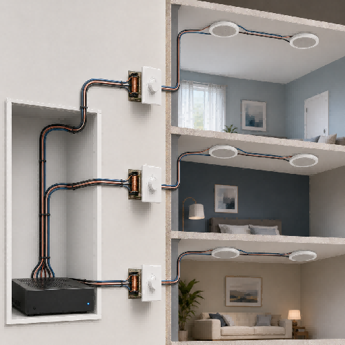
Table of Contents
- Quick Answer
- What Is an Impedance-Matching Volume Control?
- Why Multiple Speaker Pairs Can Overload an Amplifier
- Parallel Speaker Load Reference Table
- How the Impedance Multiplier Works
- A Typical Three-Room System
- Correct Wiring Topology
- Volume Control Versus Speaker Selector
- Check Amplifier Compatibility
- Check the Volume Control’s Power Rating
- Common Installation Mistakes
- Commissioning Procedure
- When a Multi-Zone Amplifier Is the Better Choice
- Conclusion
- FAQ
How Impedance-Matching Volume Controls Protect Multi-Room Ceiling Speaker Systems
Connecting one pair of 8-ohm ceiling speakers to a compatible stereo amplifier is usually straightforward. Connecting several pairs to the same amplifier outputs is not.
Every additional speaker pair wired in parallel reduces the load impedance seen by the amplifier. If that load falls below the amplifier’s minimum supported impedance, the amplifier may overheat, distort, enter protection mode, or shut down.
An impedance-matching volume control can help solve this problem. Installed between the amplifier and a room’s passive speakers, it provides local volume adjustment while increasing the apparent load impedance presented to the amplifier.
However, the protection only works when the volume control, amplifier, speaker impedance, number of zones, wiring method, power rating, and impedance-multiplier setting are correctly matched.
Quick Answer
An impedance-matching volume control is an in-wall passive control designed to perform two functions:
- Adjust the volume of a local pair of speakers.
- Help prevent multiple parallel-connected speaker pairs from presenting an excessively low impedance to the amplifier.
For identical 8-ohm speaker pairs connected in parallel, the basic load per amplifier channel is:
Total load in ohms = Speaker impedance / Number of speaker pairs
Examples:
- One 8-ohm pair presents approximately 8 ohms per channel.
- Two 8-ohm pairs present approximately 4 ohms per channel.
- Four 8-ohm pairs present approximately 2 ohms per channel.
An impedance-matching control uses an autoformer or another manufacturer-specified matching circuit to increase the apparent impedance seen by the amplifier. The correct 1X, 2X, 4X, or 8X setting must be selected according to the control manufacturer’s instructions.
What Is an Impedance-Matching Volume Control?
An impedance-matching volume control is a passive device installed between an amplifier’s speaker-level output and a pair of loudspeakers.
A typical stereo control has:
- Left-channel amplifier input
- Right-channel amplifier input
- Left-channel speaker output
- Right-channel speaker output
- Local volume adjustment
- An impedance-multiplier switch or jumper
- A published power-handling limit
Many impedance-matching controls use an autoformer. An autoformer changes the relationship between voltage and current while allowing the control to attenuate the signal delivered to the loudspeakers.
Russound describes its impedance-matching controls as autoformer-based devices intended to maintain a suitable operating load while providing local volume adjustment. Its product instructions also show that settings such as 1X, 2X, 4X, and 8X are used when different numbers of speaker pairs share an amplifier.
The exact internal circuit and setting method vary by product. Always use the installation manual for the specific control rather than assuming that every manufacturer uses identical settings.
Why Multiple Speaker Pairs Can Overload an Amplifier
A conventional stereo amplifier has two output channels:
- Left channel
- Right channel
One stereo speaker pair normally places one loudspeaker on each amplifier channel. If the loudspeakers are nominally rated at 8 ohms, the amplifier sees one nominal 8-ohm load on the left channel and one nominal 8-ohm load on the right channel.
When several stereo pairs are connected in parallel, each amplifier channel drives several loudspeakers at the same time.
For identical speaker impedances, the simplified calculation is:
Total load in ohms = Individual speaker impedance / Number of identical speakers connected to each channel
One 8-ohm speaker pair
Each channel drives one 8-ohm speaker:
8 ohms / 1 = 8 ohms per channel
Two 8-ohm speaker pairs
Each channel drives two 8-ohm speakers in parallel:
8 ohms / 2 = 4 ohms per channel
Four 8-ohm speaker pairs
Each channel drives four 8-ohm speakers in parallel:
8 ohms / 4 = 2 ohms per channel
Six 8-ohm speaker pairs
Each channel drives six 8-ohm speakers in parallel:
8 ohms / 6 = approximately 1.33 ohms per channel
These calculations use nominal speaker impedance. A real loudspeaker’s impedance changes with frequency, so its minimum impedance can be lower than the nominal value printed on the product.
The amplifier must therefore be selected and configured according to the loudspeaker manufacturer’s impedance data and the amplifier manufacturer’s minimum-load specification.
Parallel Speaker Load Reference Table
| Number of identical speaker pairs | Nominal speaker impedance | Approximate load per amplifier channel |
|---|---|---|
| 1 pair | 8 ohms | 8 ohms |
| 2 pairs | 8 ohms | 4 ohms |
| 3 pairs | 8 ohms | 2.67 ohms |
| 4 pairs | 8 ohms | 2 ohms |
| 6 pairs | 8 ohms | 1.33 ohms |
| 8 pairs | 8 ohms | 1 ohm |
This table shows the unprotected parallel load. It does not include an impedance-matching volume control or speaker-selector protection circuit.
How the Impedance Multiplier Works
An impedance-matching volume control may have multiplier settings labeled:
- 1X
- 2X
- 4X
- 8X
Conceptually, the selected multiplier increases the impedance presented toward the amplifier.
A simplified planning calculation is:
Approximate protected load = Unprotected parallel load x Impedance multiplier
For example, four identical 8-ohm speaker pairs connected in parallel create an unprotected nominal load of:
8 ohms / 4 = 2 ohms
A conceptual 4X matching setting gives:
2 ohms x 4 = approximately 8 ohms
This example explains the principle, but it is not a universal setting instruction. Product-specific charts may account for:
- Amplifier minimum impedance
- Speaker impedance
- Number of speaker pairs
- Number of controls
- Control design
- Speaker-selector protection
- Power rating
- Permitted combinations
Use the chart supplied with the selected volume control.
For example, Russound’s WALTx-2 instructions require the installer to identify the amplifier’s minimum impedance, the impedance of each speaker pair, and the total number of connected pairs before selecting the multiplier setting.
A Typical Three-Room System
Consider a residential system with:
- One stereo amplifier
- Three rooms
- One pair of 8-ohm ceiling speakers in each room
- One impedance-matching volume control in each room
- All three rooms connected to the same stereo amplifier output
Without impedance matching, the nominal load is:
8 ohms / 3 = approximately 2.67 ohms per channel
If the amplifier is only rated to operate with loads of 8 ohms or higher, directly connecting the three pairs would be outside its published requirement.
The installer must select an impedance-matching arrangement that keeps the apparent load at or above the amplifier’s minimum supported impedance.
The correct setting must be taken from the volume-control manufacturer’s chart. The installer must also confirm that the control’s power rating is suitable for the amplifier.
Correct Wiring Topology
Each room should normally have its own stereo volume control.
The signal path is:
Amplifier left and right outputs -> Room volume control input -> Room ceiling-speaker pair
For three rooms, the amplifier output is distributed to three separate controls. Each control then feeds only the speaker pair assigned to that room.
This provides:
- Independent room volume
- Clear zone identification
- Consistent impedance-matching configuration
- Easier troubleshooting
- Easier future servicing
Use four-conductor speaker cable where appropriate so that left positive, left negative, right positive, and right negative remain separate.
Do not interchange the terminals labeled “amplifier” and “speaker.” A control connected backward may not operate or protect the system as intended.
Volume Control Versus Speaker Selector
An in-wall volume control and a central speaker selector can both appear in multi-room systems, but they serve different installation needs.
In-wall impedance-matching volume control
Best suited when:
- Each room requires local volume adjustment.
- A speaker pair is permanently assigned to the room.
- The homeowner wants a simple wall-mounted control.
- A centralized app-based amplifier is not required.
Central impedance-matching speaker selector
Best suited when:
- Several speaker pairs return to one equipment location.
- Rooms need centralized on/off selection.
- A rack or cabinet is available.
- Local wall controls are unnecessary or are used separately.
Multi-zone amplifier
Best suited when:
- Each zone needs a dedicated amplifier channel.
- Independent sources are required.
- App, network, or automation control is required.
- Higher output or more predictable power per room is important.
- Future expansion is expected.
An impedance-matching control can be practical for a modest retrofit, but it is not automatically the best architecture for every whole-home audio system.
Check Amplifier Compatibility
Before installing passive volume controls, verify the following amplifier information:
- Minimum supported speaker impedance
- Rated output power at the intended impedance
- Whether multiple speaker pairs are permitted
- Whether external impedance-matching devices are supported
- Output-terminal configuration
- Protection requirements
- Instructions for bridged or bridge-tied outputs
Do not assume that every Class-D or compact wall amplifier can be connected to a traditional passive volume control.
Some amplifiers do not permit either negative speaker terminal to be connected to ground or combined with another channel. Keep left and right positive and negative conductors separate unless the amplifier and volume-control documentation explicitly permits another connection method.
Check the Volume Control’s Power Rating
Impedance matching does not make a low-power volume control suitable for an amplifier of any size.
Verify:
- Continuous power rating per channel
- Peak rating, if provided
- Permitted speaker impedance
- Permitted amplifier impedance
- Number of zones supported
- Required electrical-box depth
- Ventilation requirements
- Cable size accepted by the terminals
Do not use peak power as a substitute for a continuous power rating.
A control that is overloaded may exhibit excessive heating, distortion, mechanical noise, intermittent operation, or permanent damage.
Common Installation Mistakes
Setting every control to 1X
A 1X setting may provide little or no impedance multiplication. It may be appropriate for one speaker pair, but it may not protect the amplifier when several pairs operate simultaneously.
Selecting the multiplier by guesswork
The setting depends on the complete system. Count all speaker pairs that can operate simultaneously and use the manufacturer’s chart.
Mixing 4-ohm and 8-ohm speakers without recalculating
A 4-ohm pair places a heavier load on the amplifier than an 8-ohm pair. Mixed speaker impedances require a product-specific calculation.
Reversing the amplifier and speaker terminals
The input side must connect to the amplifier. The output side must connect to the speakers.
Combining negative terminals
Do not join left and right negative conductors unless every relevant manufacturer explicitly permits it.
Exceeding the control’s power rating
Impedance protection and power handling are separate specifications. Both must be satisfied.
Forgetting the worst-case operating condition
Design for the maximum number of rooms that can be switched on simultaneously, not the number normally used.
Using one control for several unrelated rooms
Local controls are normally installed one per speaker zone. A single control feeding multiple rooms prevents independent adjustment and complicates load planning.
Commissioning Procedure
Before applying power:
- Confirm that the amplifier is switched off.
- Label every four-conductor cable.
- Verify left and right polarity.
- Confirm the input and output sides of every control.
- Record each loudspeaker’s nominal impedance.
- Count every speaker pair that can operate simultaneously.
- Confirm the amplifier’s minimum supported impedance.
- Set all impedance-matching controls according to the manufacturer’s chart.
- Verify that each control’s power rating is adequate.
- Inspect for loose strands or shorted terminals.
- Start with all room controls at minimum volume.
- Power on the amplifier at a low master-volume setting.
- Test one room at a time.
- Activate all intended rooms and check amplifier operation.
- Listen for distortion or intermittent sound.
- Check the controls and amplifier for abnormal heating.
- Record the final settings in the project documentation.
When a Multi-Zone Amplifier Is the Better Choice
Impedance-matching volume controls are useful, but every multiplier introduces a system trade-off. The amplifier’s available power is shared among the active speaker pairs, and the actual distribution changes with room volume settings and program material.
A dedicated multi-zone amplifier is often preferable when:
- More than four or six rooms are planned.
- Every room may play loudly at the same time.
- Different sources are required in different rooms.
- Independent equalization is required.
- App or automation control is expected.
- Long-term expansion is likely.
- Precise power allocation is important.
A separate amplifier channel for each zone avoids placing many speaker pairs in parallel on one output. It also makes fault isolation and system configuration more predictable.
Conclusion
An impedance-matching volume control does more than turn a pair of ceiling speakers up or down. When correctly specified and configured, it helps keep the combined load of multiple low-impedance speaker pairs within the amplifier’s permitted operating range.
Successful design requires five verified values:
- Amplifier minimum impedance
- Speaker nominal impedance
- Number of speaker pairs
- Volume-control multiplier setting
- Volume-control power rating
Never select the multiplier by habit. Use the manual for the exact control, keep left and right conductors separate, and test the complete system under its maximum intended operating condition.
For residential projects combining Hi-Fi in-ceiling speakers, wall-mounted volume controls, mini wall amplifiers, and installed speaker cables, Lecovita can review the proposed architecture and product requirements before production or installation.
FAQ
What does an impedance-matching volume control do?
It adjusts local speaker volume while helping increase the apparent load impedance presented to an amplifier that drives multiple speaker pairs.
Can I connect four pairs of 8-ohm speakers to one stereo amplifier?
Not automatically. Four 8-ohm speakers connected in parallel to each channel create a nominal 2-ohm load. The amplifier must support that load, or an appropriate impedance-matching device, speaker selector, or multi-zone amplifier must be used.
What do 1X, 2X, 4X, and 8X mean?
They are impedance-multiplier settings. The appropriate setting depends on the amplifier, speakers, number of pairs, and control design. Follow the exact manufacturer’s setting chart.
Does lowering the wall-control volume increase speaker impedance?
Do not rely on the listening position of the volume knob as amplifier protection. Configure the impedance-matching setting for the maximum number of connected zones according to the manufacturer’s instructions.
Can one wall volume control operate several rooms?
It may be electrically possible with some equipment, but it eliminates independent room adjustment and complicates impedance and power calculations. One properly specified control per room or speaker zone is normally clearer.
Can I use an impedance-matching control with a Class-D amplifier?
Only when the amplifier and control manufacturers confirm compatibility. Never combine or ground speaker-negative terminals unless the documentation expressly permits it.
Is a speaker selector the same as a volume control?
No. A selector switches speaker zones on and off. Some selectors also contain impedance-matching protection or volume controls, but these functions must be verified in the product specifications.
Is a multi-zone amplifier better?
It is often better for larger systems, independent sources, app control, predictable power per room, and future expansion. Passive impedance matching remains useful for simpler retrofit installations.
