
Voltage vs. Fidelity: The Evolution of Commercial 70V and Direct-Drive Amplification

About Author: Kevin Wu
Founder & Principal Audio Engineer, LECOVITA
Specialize in acoustic engineering, high-fidelity speaker and amplifier design, precision manufacturing, sonic innovation, immersive audio solutions, and premium audio system development.
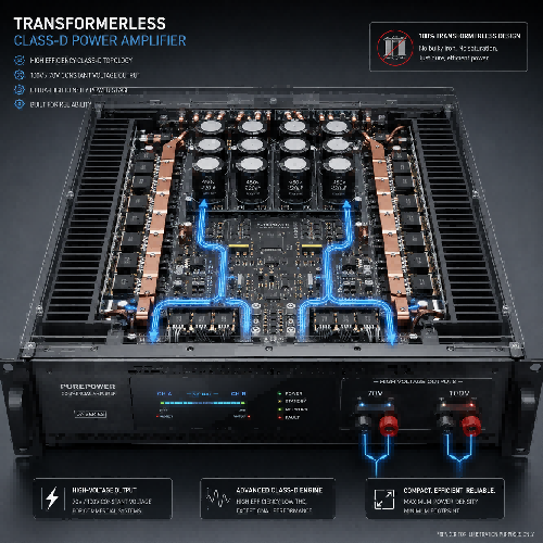
Table of Contents
Voltage vs. Fidelity: The Evolution of Commercial 70V and Direct-Drive Amplification
Distributing audio over hundreds of meters in large commercial facilities faces a primary physical hurdle: $I^2R$ electrical copper resistance loss. Traditional 70V/100V constant-voltage systems solve this by stepping up voltage and stepping down current through transformers, allowing long daisy-chained speaker runs. However, audio transformers can suffer from low-frequency core saturation and insertion loss. Modern commercial audio engineering solves this tradeoff by deploying high-voltage, transformerless direct-drive Class-D DSP amplifiers that send high-voltage signals straight to the line with studio-grade fidelity.
The Infrastructure Dilemma: Copper Loss in Large Spaces
In low-impedance ($4\,\Omega / 8\,\Omega$) residential audio systems, speaker wire runs are short, keeping resistance low. However, in a multi-story hotel, airport terminal, or retail center where wire runs exceed 100 meters, driving low-impedance speakers directly creates massive power loss.
According to Joule's Law ($P = I^2R$), power loss across a wire cable is proportional to the square of the current ($I$). If you send high current through a long cable to power an $8\,\Omega$ speaker, most of the amplifier's wattage turns into heat inside the wall conduit before it ever reaches the driver. To deliver clean audio across vast facilities without using heavy gauge copper cables, commercial audio relies on high-voltage distribution principles similar to municipal power grids.
[Low-Impedance 8-Ohm Run]  ===> High Current (I)  ===> Massive Heat & Cable Power Loss
[70V/100V Constant-Voltage] ===> High Voltage (V) ===> Ultra-Low Current (I) & Long-Distance Punch
1. Constant-Voltage Physics: How 70V/100V Line Transformers Work
A constant-voltage system operates by stepping up the amplifier's output voltage to a standardized peak of $70.7\text$ (common in North America) or $100\text$ (common in Europe and Asia).
By stepping up the voltage at the amplifier, the current ($I$) required to deliver the same wattage drops significantly. This allows integrators to run thin 18-gauge or 16-gauge wire over long distances with minimal signal loss. At each speaker location, a small step-down transformer converts the high-voltage line back down to a safe low-voltage signal for the voice coil.
However, traditional magnetic transformers introduce physical compromises:
-
Core Saturation: At low frequencies ($<60\text$), the iron core of a cheap transformer can magnetically saturate, creating severe harmonic distortion and muddying bass response.
-
Insertion Loss: Magnetic hysteresis inside the transformer consumes $0.5\text$ to $1.5\text$ of dynamic output power.
-
Frequency Roll-off: Micro-windings can attenuate high frequencies above $15\text$, limiting air and clarity.
2. Direct-Drive Transformerless Class-D Innovation
To eliminate the distortion, physical weight, and frequency limits of traditional transformers, modern high-end commercial amplifiers deploy Direct-Drive Transformerless Class-D Topologies.
                   [High-Voltage DC Power Rail]
                                 │
              ==============[Direct-Drive Class-D FETs]=============
              (Switches up to 70V/100V RMS natively without transformers)
  ====================[Long Copper Speaker Cable]====================
                                 │
                                 ▼
          [Direct Full-Range Frequency Spectrum (20Hz - 20kHz)]
Instead of using a bulky internal iron-core output transformer to boost voltage, direct-drive amplifiers utilize high-voltage internal DC power rails ($>100\text$) paired with high-speed MOSFET switching transistors. The amplifier natively outputs a high-voltage $70\text$ or $100\text$ RMS signal directly from its silicon output stage.
By bypassing the transformer entirely, direct-drive amplifiers retain a flat frequency response from $20\text$ to $20\text$, deliver exceptional damping factor, and preserve deep, punchy low-end down to sub-bass registers.
System Architecture Comparison: Traditional Transformer vs. Direct-Drive Class-D
| Engineering Factor | Traditional Transformer 70V/100V Systems | Direct-Drive Class-D DSP Amplifiers |
| Output Transformer | Required (Adds weight, heat, and core saturation) | None (100% Transformerless native high-voltage output) |
| Frequency Response Range | Often limited ($70\text – 15\text$) | Full-range audiophile bandwidth ($20\text – 20\text$) |
| Damping Factor & Bass Control | Low (Damped by transformer impedance) | High (Tight, articulate woofer cone control) |
| Amplifier Energy Efficiency | Moderate ($65\% – 75\%$) | Ultra-High ($90\% – 95\%$ Class-D efficiency) |
| Rack Space & Heat Output | Heavy, bulky chassis requiring active cooling | Compact (1U/2U high-density rack units, low thermal load) |
| Integrated DSP Capability | Basic analog volume taps | Advanced digital FIR filters, limiting, & zone routing |
3. Engineering Decision Matrix for B2B Commercial Integrators
Selecting between low-impedance direct drive, traditional transformer 70V, and modern direct-drive Class-D depends on the specific project scope:
-
High-Fidelity Hospitality & Retail (Direct-Drive 70V/100V): Use direct-drive Class-D 70V amplifiers when the client demands rich background/foreground music with deep bass (e.g., luxury hotel lounges, boutique stores) across distributed speaker lines.
-
Massive Distributed Paging (Standard 70V Transformer): Ideal for basic voice paging and speech privacy across hundreds of low-wattage ceiling speakers in corridors, airports, and warehouse facilities.
-
Dedicated Performance Zones (Low-Impedance $4\,\Omega/8\,\Omega$ Direct): Best reserved for dedicated high-SPL spaces like auditoriums, sports bars, and performance venues where cable runs are short and maximum power transfer is required.
Expert Q&A
Q1: How do you calculate total amplifier power required for a 70V commercial system?
A: Calculating 70V amplifier power is straightforward thanks to parallel transformer taps. Simply add up the wattage tap settings of all connected speakers on the line. For example, if you have 20 in-ceiling speakers tapped at $7.5\text$ each, your total load is $150\text$ ($20 \times 7.5\text$). Always add a 20% headroom safety buffer to account for line loss and dynamic peaks, meaning you should specify an amplifier capable of delivering at least $180\text$ RMS.
Q2: What happens if an installer accidentally connects an $8\,\Omega$ speaker directly to a 70V amplifier line?
A: Connecting a low-impedance $8\,\Omega$ speaker directly to a $70\text$ line without a step-down transformer will draw excessive current ($P = V^2 / R = 70.7^2 / 8 \approx 624\text$). This massive load will instantly trigger the amplifier's short-circuit protection, or burn out the speaker's delicate voice coil within seconds. Always verify transformer taps before powering up a 70V/100V commercial line.
Q3: Can direct-drive Class-D amplifiers power both 70V commercial lines and $8\,\Omega$ low-impedance speakers simultaneously?
A: Yes! Premium multi-channel commercial DSP amplifiers—such as LECOVITA's commercial DSP matrix series—feature software-selectable output modes per channel. An integrator can set Channel 1 to drive a $70\text$ high-density ceiling speaker loop in a restaurant dining room, while setting Channel 2 to drive a low-impedance $4\,\Omega$ subwoofer under the bar, all from a single compact rack chassis.
